
2012-07-18
Alright, I have fixed thumb4 problem to thumb5. I actually have no idea why it became bigger and couldn't fit wriargeV3 anymore. But I can't seem to upload it to thingiverse on the moment. It's been three days. I am located with a very poor internet connection at the moment. Hope this won't be long. Be patient, or if you are so desperate, go to thingiverse and send me your email, I will return you the STL.
2012-06-26
I finally updated all fingers hinges to make it much easier for assembly. If you have an acurate printer there shouldn't be anymore filling nor drilling. Although I have a quality reputated printer, holes shrink a little because of the overhang. I tried of making snap in parts like suggested Easton Lachapelle, but with the test I did, the strength of the traction exerced by the rods would disassemble the hinges.
Anyway, I received the AS5040 Magnetic encoders ordered for the big servos. Soon time for electronics and adventure I really don't know much about...
Also trying to teach InMoov with voice recognition, and object detection. I'm far still from any good result. My camera is not even detected by the software myrobotlab, but the voice gives results. I tried to make him say something before he starts the action but I get really confused in some implementation for now. Those new softwares and concepts have to make their way in my brain first before to be applied to InMoov.
Here is a little video:
There is someone that needs your interest at the moment, he has done a great job on producing a printable hand in one piece if I understand right. He plans on creating another version you can discover.
He has launched an indiegogo campaign here
http://anthromod.com/blog/?attachment_id=247
2012-06-23
I have uploaded on Thingiverse "robcap3V1" and "leftrobcap3V1" for to close the elbow of the forarm. This part is necessary if you plan to go on with the project of the complete arm. It also gives a finishing touch to the forarm...
 |
| Here you see it attached to the forarm, with the "elbowshaft1" glued on it. |
 | |||
| It needs to be glued to "robpart5V2" or "leftrobpart5V2" depending on which arm you built. |
 |
| Here you see where they are meant to be used. |
2012-06-22
I have uploaded on thingiverse the new brackets for the servos in the forarm. Here are the instructions for to adapt them inside. These let you decide wether you want to add a fifth servo allowing animation of all the fingers or if you rather keep the Arduino Uno inside the forarm.
I would advise you, if you plan on building the complete arm (biceps and shoulder) to remove the arduino Uno from inside the forarm and get the pinky finger giggling around!
 | |
| If you just printed the parts, you can go ahead and remove all the brackets from "robpart3 and robpart4V2" or "leftrobpart3 and leftrobpart4V2" with pliers. If you have already glued these parts together, it will be a bit more tricky but I did it, so I'm sure you can. |
 | |
| This is on "robpart3" |
 | ||
| Do the same treatment to "robpart4V2" | . |
 | |
| Glue in "stand2" at the place of the Arduino. Make sure the servo actuator will be free to rotate with the rods. Notice the servo (pinky) comes from the back of the bracket. You might want to tight the servo before gluing or drill holes on the side of the forarm for to have access with a screwdriver. |
 |
| You should have something like this now. Here you see the servo(index) |
 |
| Set in the servo (thumb) that is half way in "robpart1 or rotawrist". (Sorry on this picture all the cables and actuators are already fixed in, this is due to a lack of the correct photo.) |
 |
| You should have now three servos aligned in the forarm with the two new brackets set above. Thumb, index , pinky.(again sorry for the lack of picture) |
 |
| Set above the servo (majeure) as shown. |
 |
| Attach the last above servo (ringfinger) in it's bracket. |
 | ||
| Run the nylon rods as shown. Rods run a bit differently now. |
 |
| I hope the following pictures help you to figure out how rods run. Again, it doesn't have to be that way, you might come out with a much better solution. |


2012-06-17
Rotational wrist printed for robot
I have uploaded the parts for the rotational wrist on thingiverse. This is a nice little extra feature.
see:http://www.thingiverse.com/thing:25149
I also have modified the servo brackets in order to have five movable fingers.
This means the Arduino is going to be set on the arm instead of inside the forarm. This modification also makes it much more easy to access the servos because the cover doesnt' hold any more servos. Which means the cover is a cover and only a cover.(Suggestion of Brian from Pittsburgh).
I will soon upload the new brackets. I made this modification as less invasive as possible. That means if you have already printed the whole thing, you won't have to reprint all the parts but only the new brackets.

2012-06-09
Nice day today, InMoov right hand has been featured on Thingiverse!
I wanted since a while to transform the wrist of the hand because of a lack of DOF. For to do that, I had to dismantle the whole hand...(again) I decided last night to give it a go. Worked something in Blender after creating some gears with Openscad using "Parametric Herringbone and helical gears" from canadaduane in Thingiverse. Actually since it was the first time I used Openscad, it took me a while to figure out the whole thing.
I printed the parts this morning and made a test with the Arduino. I had to adjust some parts of course but the whole thing finally works. I will soon put the parts to download on Thingiverse.
Here are some pictures to illustrate the building of this new part.
 | |
| After printing you should have five parts. |
 |
| Remove with pliers the support. Fix in the bracket the servo MG995. Use the Arduino to set it to 0 degree. |

 |
| Use one of your spare actuator from your servo. Cut it and fix it to the small gear as shown. It shouldn't be oversized. |
 |
| Grease the big gear before setting in "rotawrist2". |

 |
| Drill and tight fit the gear to "rotawrist3" through "rotawrist2". |
 | ||
| Use hot glue gun to position and fix "cableholderwrist1" to the top of the servo. This will help to guide the rods into the center hole. |
 |
| Close the whole thing and tight the 3 screws on perimeter. Make a test run with your Aduino. This is the position you should have when your servo is at 180° for the left hand |
 |
| Now it's time to glue "rotawrist1" to "robpart2V2". Once glued detach "rotawrist1" from "rotawrist2". Start running the rods from your servos up to each finger. (Use the Arduino to set your servos at 0 Degrees) Don't twist the rods and make sure the upper rods run through the upper parts of the fingers, run the lower rods through the lower parts of the fingers. |
 |
| This is where you are going to test your patience and skills. I use twisers for to do the job. |
2012-05-25
Arduino test with robot arm
Today was a big day, I finally got the new Arduino, unfortunatly it isn't the Uno that I ordered but the Mega. Well it means I can put even more servos in the beast!
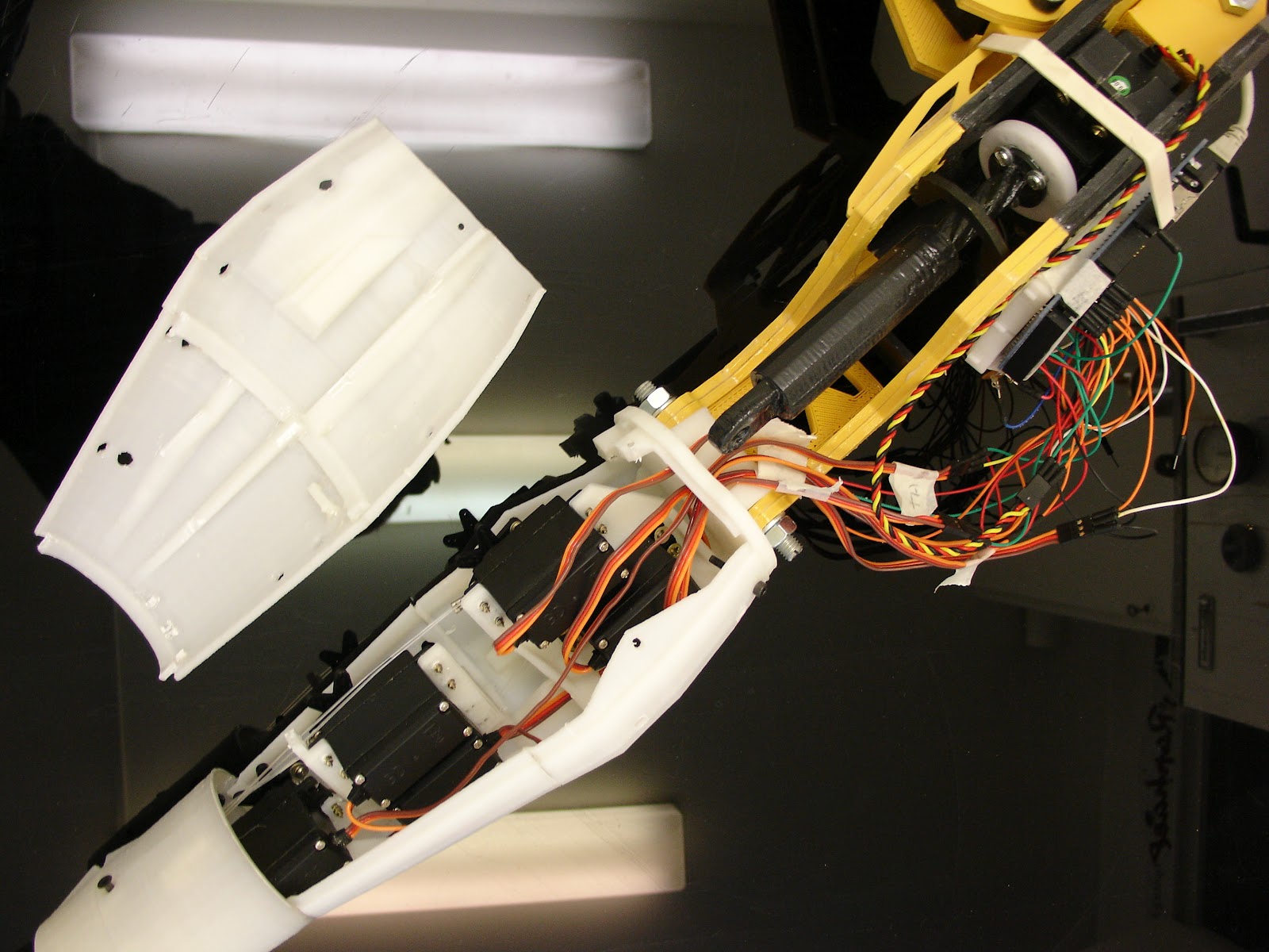
So after waiting such a long time, now time for testing, because I had serious doubts about the strength of the servos Hitec HS 805BB. The piston I have designed is obviously something that use a lot of torque, if I could work out to make "supermodified" servos all my doubts would vanish. I have not enough electronic knowledge for to do that yet.
Anyway I was happily surprised when I first plugged the arm and saw that it actually pulled up the whole thing at once.
It makes me want to go further in the design.
So after waiting such a long time, now time for testing, because I had serious doubts about the strength of the servos Hitec HS 805BB. The piston I have designed is obviously something that use a lot of torque, if I could work out to make "supermodified" servos all my doubts would vanish. I have not enough electronic knowledge for to do that yet.
Anyway I was happily surprised when I first plugged the arm and saw that it actually pulled up the whole thing at once.
Subscribe to:
Posts (Atom)